If you had asked me before spring of 2017 if thermostat replacements or headlight upgrades were in my near future, I would probably have replied “Hell no, that kind of stuff is in my dim past”. I swore that when I could afford it, I would never change the oil or replace the brake shoes again. But when you buy a car like a 66 Mustang, you quickly find yourself looking for the Gojo. And grabbing your wallet (or slapping leather, as we used to say.)
The first thing I did was to put it in the shop for a paint job. When I received it the paint was bubbled and cracked. Now it’s smooth and shiny. While it was in the body shop, I contacted a local mechanic who specializes in older cars and trucks and started the ball rolling to add power steering, power brakes and air conditioning. However, as a one man shop, he is backed up and I am awaiting my time in the barrel.
Update on the mechanic work. If you want someone to work on your Mustang, you need to find a Mustang man or at least a Ford man. Turns out that the mechanic I was directed to was a Chevy man. I did not find this out until he had started the process. He got the power steering done along with a replacement steering column by Ididit. He also got the compressor mounted for the AC but never got to the under dash unit. Not to mention the wiring harness replacement. (I found the wiring to be a mish mash of twisted wires, electrical tape and brittle insulation.) After waiting a year for him to get to my project and being told repeatedly that he would never work on another Mustang, I finally found a new mechanic. My new man is now in the process of finishing up the AC, installing the the new main harness and replacing the Ididit column with the original column. First, the Ididit column was a piece of crap that would hang up when I turned and did not cancel my turn signals. But more importantly it would not accommodate my Rally Pac. Not only does the Rally Pac look good, but it adds $2000-3000 to the value of the car. Seems my Chevy man suspected that from the beginning but did not mention it. Instead I had to find out for myself. (See below for my Rally Pac refurb.) Still don’t have the power brakes, but that can wait.
Meanwhile, I’ve taken on a few projects of my own. The horn didn’t work nor did the dash lights. The horn problem was simple. Some adjustments at the steering wheel hub and application of pliers to the connectors soon had them honking, feebly but at least they sound off.
Project 1 - 66 Mustang Colorized Wiring Diagrams
The gauges didn’t seem to work as they should (particularly the amp meter) and the dash lights were so dim I could not see the gauges even at night. My first step was to replace the constant voltage module that fed the gauges and replace the bulbs and blue lenses. This required getting into the dash and the rats nest of 50 year old wiring complete with wire wrapped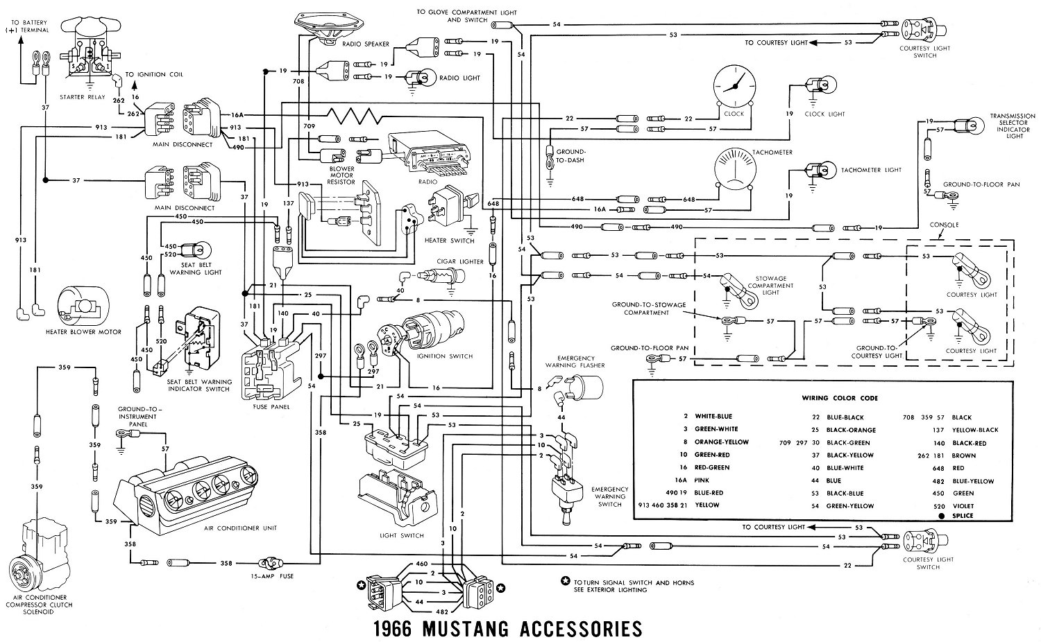 connections and electrical tape so old the sticky was gone! What I needed was a wiring diagram. As usual, ask Google and you will receive. I soon had a set of old black and white diagrams. However, these required that I continually refer to the legend for the color code. What I needed was a set of real COLOR CODED schematics. While color coded schematics can be purchased (even a CD) I decided to create my own.
First I found an old overall b&w schematic that was divided into two pages. So I “welded” them together and imported the combined jpeg into AutoCAD. I spent most of a day developing a couple of lisp routines, one to draw multicolored lines and another to label them with the Ford numeric legend. I spent a couple of days digitizing the schematics. After realizing that the schematic I had did not agree with the earlier versions, I spent another day truing up the overall schematic. But before I could do that, I had realized that the overall schematic looked at the Mustang with the front to the right and the rear to the left and the right side of the car to the bottom while the individual schematics were oriented just the opposite with the front to the left and the right to the top. Fortunately, AutoCAD could correct this with a couple of Mirror commands..jpg)
Next I realized that a few sub-systems were missing, specifically the fog lights and the Rally Pac (tach and clock). So I had to modify the schematic to include these. And, while I was at it I corrected the connections through the two main disconnects. (The Mustang has two main disconnects, one to the left of the brake master cylinder that feeds the headlights and one to the right of the brake master cylinder that feeds the instruments.)
Next I pulled up each individual schematic and over-drew the wiring with color coded lines. Now I have a set of individual schematics and an overall that ties them all together. To view/download the pdf file click on the diagram below. If you find any errors or omissions, please let me know by clicking here to .
After working with the rat’s nest that is the original wiring, I decided to upgrade most all of the wiring. For the main harness, I selected the 1966 UNDER-DASH HARNESS W/ PREMIUM FUSE BOX AND RELAYS from CJ Pony Parts with blade fuses. To my chagrin, when I opened the box there was NO CIRCUIT DIAGRAM. After several queries to CJ’s customer service with no results of value, I called Scott Drake, the manufacturer, directly to enquire about a circuit diagram. Scott wasn’t available but one of his employees told me that there was no specific diagram for this harness but that the classic diagram would work ok -
 for the small price of $12.95. I felt like a kid on Christmas morning with a box of new bike parts and no instructions. And a call to the manufacturer got the reply “Oh, we didn’t know you wanted to ride it but we would be glad to provide instructions…for a price”.
So I took a copy of my classic wiring diagram, the new harness and a circuit tester and had at it. While the classic diagram is close, there are a couple of additional relays and a few subtle but significant changes in the wire colors. So much for Scott’s advice. (I know a real wiring diagram exists somewhere because the harness could not be made without it.)
So, you are welcome to pay $12.95 for a bound book of schematics (that may not really match your harness) or you can download the above pdf for free. The diagrams are formatted to print on 11x17 paper, but can be printed on 8½ x11 though the large schematics are a stretch (or, actually, a squeeze).
Update - I now have created a set of wiring diagrams for the 64½ and the 65 Mustangs. And, as time allows, I hope to add later models. Just click here for the links.
Project 2 - 12vdc Power Port and USB Ports
All modern cars have power ports, sometimes referred to as cigarette lighters, to power our toys - cell phones, game boys, tablets, etc. 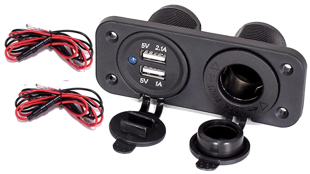 The Mustang has only one (which is actually referred to as a cigar lighter) and it is wired to be always on, a trait not really desirable in a power port. And in my case, the cigar lighter didn’t work. Probably just a blown fuse (more on that later.) I could easily rewire the lighter to an accessory circuit which would have solved both problems, but, as always, I look for the more elegant solution. (Some of my former employees might recall lectures about the “elegant solution” whether it be engineering or lines of computer code and their affects on my endorphins.)
First, a search of Amazon found this combo lighter socket/dual USB outlet for use on a 12vdc system. Cost - $10. My first attempt was to cut holes in the ash tray rather than my dashboard. I quickly found that I had to remove part of the tray box to accommodate the screws and then the plate over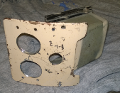 the ash tray to make more room. I cut the holes with my drill and a hole saw. I didn’t really like the final look. (See picture to right.) Fortunately, the ash tray can be replaced for a few bucks.
Looking for an alternative, I came across a 12x12 25mil sheet of 6061T6 aluminum on Amazon. 6061 aluminum alloy is readily bendable and the 25mil (0.025 inch) thickness can be easily shaped but still is rigid enough to stand up to normal wear.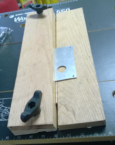 And at $11.25 per sheet, reasonably priced. To cut the sheet you have several choices. Perhaps a carbide blade on a circular saw or a metal blade on a jig saw. I opted for a Dremel with a metal cutting wheel. This proved to be less than desirable when trying to cut a straight line free hand. So I bought a Dremel router attachment and a tungsten carbide cutter. I used it with my home made press brake (see below) as a routing jig.
I decided that the more elegant solution would be a shaped aluminum piece that would present the outlets vertically which would call for bending the cut aluminum sheet. You could just put your sheet in a vice and bend it. Having no vice, I opted to create my own press brake. I used a 1x6x8’ oak board I had laying around (you can get one at Lowe’s), a 12” hinge and a pair of T-handle bolts . Cut the board into 3 equal lengths of 16” each, lay two of the cut boards together and drill holes and mount the T-handle bolts near the ends. You want to leave room between the bolts to slide your aluminum sheet between and then clamp down with the T-handle bolts. Then mount the hinge along the bottom board and then to 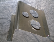 the third board in such a way that the third board will fold up against the top board at 90º. The picture to the left should clarify this. Don’t be surprised if you have to remount the hinge a couple of times to get it right. I would suggest just mounting the two end screws until you are satisfied with the action.
With the brake, I fashioned the aluminum contraption to the right. I thought that it would be much better if the outlets were vertical. However this actually stuck out too far from the dashboard. So I opted for a simple flat sheet without any angles. (So much for the press brake. However, I used it for a clamp to cut the sheet with the router.) The final version is on the left. I painted it with some Krylon flat black rattle can paint. (I will be redoing the interior to black so the dash will be black.) I also purchased a USB outlet that displays the battery voltage. Click the picture for a blow up.
You will note on the right of the picture is a Kinivo. This is a hands free Bluetooth device that connects with the phone and includes a mini plug output to play to another device. I have utilized a male-male mini panel mount plug which mounts to the aluminum sheet. My radio has an auxiliary input with an RCA to mini cable. This allows me to utilize my phone to play my music through my radio and even answer my phone, though the road noise of the convertible makes conversation difficult.
Project 3 - “Ding! Lights are on!”
Car tech has changed a lot in the last 50 years! I mean, when I got in for the test drive and put the Mustang in reverse, I looked for the backup camera! (In 1966 backup cameras would be classified as alien technology.) So when I drove it home I turned on the lights (I like driving lights). But when we stopped for some lunch, I returned to find the lights still on and dim. Fortunately, it cranked up fine (but I had jumper cables just in case). So I decided I needed a "lights on" warning.
Checking with Google, I found plenty of simple warning systems based on the time honored ding-ding alarm. But I owned several Nissan Maximas (Maximi?) back in the 80s that had a sexy voice that said things like “(beep) Lights are on” and “(beep) Fuel is low” and “(beep) The door is ajar”. So first I went hunting for a device that would play a message rather than just a beep. I hit the jackpot with the PUI Audio API-4260-LW150-R . This little device, about 1½ in diameter and 1 inch high has a USB port and will record a message up to 30 seconds in length, either wav or mp3 format. Put 7-24vdc across the leads and it plays back the audio file.
Now I needed an appropriate message. The only car related audio files I could find generally were some form of “burning rubber”. I yearned for the chick from my Maxima back in the 80s. Finally I stumbled across some guy with more time than sense who had obtained an audio unit from a junked Maxima. And he played all of the messages on a YouTube video. I quickly ripped the entire audio file and sliced out the lights segment. For a little nostalgia, click here.
I tried to set up the device without using a relay but the voltages just wouldn’t work out. What I needed was a relay with a normally closed contact. For the uninitiated, the “normal” position of a relay with no power to the coil. There are two basic types - normally open (NO, also known as a form a relay) and normally closed (NC, also known as a form b relay). What I needed was a NC relay which would be 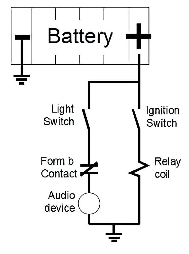 closed when the ignition is off. This would complete the circuit between the lighting circuit, the voice device and ground thus making the voice device play its message. See the circuit diagram.
When the Light Switch is ON and the Ignition Switch is OFF, the Form b Relay will be closed and there will be a path to ground through the Audio Device. If the Ignition Switch is ON, the Form b Contact is open and the Audio Device is de-energized.
Of course, it’s not that simple. Form a relays are common as matter whereas Form b relays are as scarce as anti-matter. The only Form b relay I found was about $35 vs $3.50 for a Form a relay. Fortunately, a third form of relay exists - the Form c. A Form c relay has both Form a and Form b contacts. And Radio Shack came through with a Form c relay for $3.12 (currently available from Amazon). (I opted for an electronic relay because of if size and weight. The alternative is an electromechanical “ice cube” relay, larger and heavier. The “ice cube” relay has its applications as you will see later.)
To package it all up, I found a black plastic project box by Hammond that would allow me to squeeze the Audio Device, the relay and a Molex connector into one small box. I cut a hole in the top to give the sound somewhere to come out. The total cost was less than 50 bucks, but the final product, at least to me, was priceless.
Connect the Light Switch wire to either the black or the red/yellow wire on the light switch. The black wire will alarm if the headlights or parking lights are on. The red/yellow will alarm only if the headlights are on. The coil wire can be connected to any wire that’s on when the Ignition Switch is on except the dashboard light circuit which is subject to dimming.
Project 4 - Running Lights
I prefer to have some type of running lights on when I am driving. (But NOT the parking lights. Distance perception to on-coming drivers is affected with parking lights. And they are not visible at any distance in rain or fog. It is not recommended that you drive with just the parking lights on. After all, they are called PARKING lights for a reason.) Since I have a GT with Fog Lights, I choose the Fog Lights. (If you do not have fog lights, 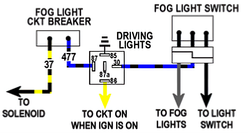 you can drive with head lights ON but then you will need a “Ding! Lights are on!” box so you won’t leave them on when you stop the engne.)
This is much simpler than the “lights are on” project. All you need is an “ice cube” electromechanical relay (also referred to as an “automotive relay”). This is a Form c relay, having both a NO and a NC contact. Insert the NO (Form a) contact, labeled 87 and 30, in the blue/black fog light circuit between the circuit breaker and the switch. Tie the coil leg, labeled 86, to any circuit that is ON when the Ignition Switch is ON and the other side of the coil, labeled 85, to ground. Now, if you keep the Fog Light switch ON, the Fog Lights will be on when the Ignition Switch is ON and off when it is OFF. Unfortunately, they will also come on when the ignition switch is in Acc. (You can simply flip the switch off.) However, if you have the “Ding! Lights are on!” box, it will remind you.
Note that if you have factory installed Fog Lights, your dash lights will be on when your Running (Fog) Lights are on.
The first thing I did was to put it in the shop for a paint job. When I received it the paint was bubbled and cracked. Now it’s smooth and shiny. While it was in the body shop, I contacted a local mechanic who specializes in older cars and trucks and started the ball rolling to add power steering, power brakes and air conditioning. However, as a one man shop, he is backed up and I am awaiting my time in the barrel.
Update on the mechanic work. If you want someone to work on your Mustang, you need to find a Mustang man or at least a Ford man. Turns out that the mechanic I was directed to was a Chevy man. I did not find this out until he had started the process. He got the power steering done along with a replacement steering column by Ididit. He also got the compressor mounted for the AC but never got to the under dash unit. Not to mention the wiring harness replacement. (I found the wiring to be a mish mash of twisted wires, electrical tape and brittle insulation.) After waiting a year for him to get to my project and being told repeatedly that he would never work on another Mustang, I finally found a new mechanic. My new man is now in the process of finishing up the AC, installing the the new main harness and replacing the Ididit column with the original column. First, the Ididit column was a piece of crap that would hang up when I turned and did not cancel my turn signals. But more importantly it would not accommodate my Rally Pac. Not only does the Rally Pac look good, but it adds $2000-
Meanwhile, I’ve taken on a few projects of my own. The horn didn’t work nor did the dash lights. The horn problem was simple. Some adjustments at the steering wheel hub and application of pliers to the connectors soon had them honking, feebly but at least they sound off.
Project 1 -
The gauges didn’t seem to work as they should (particularly the amp meter) and the dash lights were so dim I could not see the gauges even at night. My first step was to replace the constant voltage module that fed the gauges and replace the bulbs and blue lenses. This required getting into the dash and the rats nest of 50 year old wiring complete with wire wrapped
connections and electrical tape so old the sticky was gone! What I needed was a wiring diagram. As usual, ask Google and you will receive. I soon had a set of old black and white diagrams. However, these required that I continually refer to the legend for the color code. What I needed was a set of real COLOR CODED schematics. While color coded schematics can be purchased (even a CD) I decided to create my own.First I found an old overall b&w schematic that was divided into two pages. So I “welded” them together and imported the combined jpeg into AutoCAD. I spent most of a day developing a couple of lisp routines, one to draw multicolored lines and another to label them with the Ford numeric legend. I spent a couple of days digitizing the schematics. After realizing that the schematic I had did not agree with the earlier versions, I spent another day truing up the overall schematic. But before I could do that, I had realized that the overall schematic looked at the Mustang with the front to the right and the rear to the left and the right side of the car to the bottom while the individual schematics were oriented just the opposite with the front to the left and the right to the top. Fortunately, AutoCAD could correct this with a couple of Mirror commands.
Next I realized that a few sub-
Next I pulled up each individual schematic and over-
After working with the rat’s nest that is the original wiring, I decided to upgrade most all of the wiring. For the main harness, I selected the 1966 UNDER-
NO CIRCUIT DIAGRAM. After several queries to CJ’s customer service with no results of value, I called Scott Drake, the manufacturer, directly to enquire about a circuit diagram. Scott wasn’t available but one of his employees told me that there was no specific diagram for this harness but that the classic diagram would work ok -So I took a copy of my classic wiring diagram, the new harness and a circuit tester and had at it. While the classic diagram is close, there are a couple of additional relays and a few subtle but significant changes in the wire colors. So much for Scott’s advice. (I know a real wiring diagram exists somewhere because the harness could not be made without it.)
So, you are welcome to pay $12.95 for a bound book of schematics (that may not really match your harness) or you can download the above pdf for free. The diagrams are formatted to print on 11x17 paper, but can be printed on 8½ x11 though the large schematics are a stretch (or, actually, a squeeze).
Update -
Project 2 -
All modern cars have power ports, sometimes referred to as cigarette lighters, to power our toys -
The Mustang has only one (which is actually referred to as a cigar lighter) and it is wired to be always on, a trait not really desirable in a power port. And in my case, the cigar lighter didn’t work. Probably just a blown fuse (more on that later.) I could easily rewire the lighter to an accessory circuit which would have solved both problems, but, as always, I look for the more elegant solution. (Some of my former employees might recall lectures about the “elegant solution” whether it be engineering or lines of computer code and their affects on my endorphins.)First, a search of Amazon found this combo lighter socket/dual USB outlet for use on a 12vdc system. Cost -
the ash tray to make more room. I cut the holes with my drill and a hole saw. I didn’t really like the final look. (See picture to right.) Fortunately, the ash tray can be replaced for a few bucks.Looking for an alternative, I came across a 12x12 25mil sheet of 6061T6 aluminum on Amazon. 6061 aluminum alloy is readily bendable and the 25mil (0.025 inch) thickness can be easily shaped but still is rigid enough to stand up to normal wear.
And at $11.25 per sheet, reasonably priced. To cut the sheet you have several choices. Perhaps a carbide blade on a circular saw or a metal blade on a jig saw. I opted for a Dremel with a metal cutting wheel. This proved to be less than desirable when trying to cut a straight line free hand. So I bought a Dremel router attachment and a tungsten carbide cutter. I used it with my home made press brake (see below) as a routing jig.I decided that the more elegant solution would be a shaped aluminum piece that would present the outlets vertically which would call for bending the cut aluminum sheet. You could just put your sheet in a vice and bend it. Having no vice, I opted to create my own press brake. I used a 1x6x8’ oak board I had laying around (you can get one at Lowe’s), a 12” hinge and a pair of T-
the third board in such a way that the third board will fold up against the top board at 90º. The picture to the left should clarify this. Don’t be surprised if you have to remount the hinge a couple of times to get it right. I would suggest just mounting the two end screws until you are satisfied with the action.With the brake, I fashioned the aluminum contraption to the right. I thought that it would be much better if the outlets were vertical. However this actually stuck out too far from the dashboard.
So I opted for a simple flat sheet without any angles. (So much for the press brake. However, I used it for a clamp to cut the sheet with the router.) The final version is on the left. I painted it with some Krylon flat black rattle can paint. (I will be redoing the interior to black so the dash will be black.) I also purchased a USB outlet that displays the battery voltage. Click the picture for a blow up.You will note on the right of the picture is a Kinivo. This is a hands free Bluetooth device that connects with the phone and includes a mini plug output to play to another device. I have utilized a male-
Project 3 -
Car tech has changed a lot in the last 50 years! I mean, when I got in for the test drive and put the Mustang in reverse, I looked for the backup camera! (In 1966 backup cameras would be classified as alien technology.) So when I drove it home I turned on the lights (I like driving lights). But when we stopped for some lunch, I returned to find the lights still on and dim. Fortunately, it cranked up fine (but I had jumper cables just in case). So I decided I needed a "lights on" warning.
Checking with Google, I found plenty of simple warning systems based on the time honored ding-
Now I needed an appropriate message. The only car related audio files I could find generally were some form of “burning rubber”. I yearned for the chick from my Maxima back in the 80s. Finally I stumbled across some guy with more time than sense who had obtained an audio unit from a junked Maxima. And he played all of the messages on a YouTube video. I quickly ripped the entire audio file and sliced out the lights segment. For a little nostalgia, click here.
I tried to set up the device without using a relay but the voltages just wouldn’t work out. What I needed was a relay with a normally closed contact. For the uninitiated, the “normal” position of a relay with no power to the coil. There are two basic types -
closed when the ignition is off. This would complete the circuit between the lighting circuit, the voice device and ground thus making the voice device play its message. See the circuit diagram.When the Light Switch is ON and the Ignition Switch is OFF, the Form b Relay will be closed and there will be a path to ground through the Audio Device. If the Ignition Switch is ON, the Form b Contact is open and the Audio Device is de-
Of course, it’s not that simple. Form a relays are common as matter whereas Form b relays are as scarce as anti-
To package it all up, I found a black plastic project box by Hammond that would allow me to squeeze the Audio Device, the relay and a Molex connector into one small box. I cut a hole in the top to give the sound somewhere to come out. The total cost was less than 50 bucks, but the final product, at least to me, was priceless.
Connect the Light Switch wire to either the black or the red/yellow wire on the light switch. The black wire will alarm if the headlights or parking lights are on. The red/yellow will alarm only if the headlights are on. The coil wire can be connected to any wire that’s on when the Ignition Switch is on except the dashboard light circuit which is subject to dimming.
Project 4 -
I prefer to have some type of running lights on when I am driving. (But NOT the parking lights. Distance perception to on-
you can drive with head lights ON but then you will need a “Ding! Lights are on!” box so you won’t leave them on when you stop the engne.)This is much simpler than the “lights are on” project. All you need is an “ice cube” electromechanical relay (also referred to as an “automotive relay”). This is a Form c relay, having both a NO and a NC contact. Insert the NO (Form a) contact, labeled 87 and 30, in the blue/black fog light circuit between the circuit breaker and the switch. Tie the coil leg, labeled 86, to any circuit that is ON when the Ignition Switch is ON and the other side of the coil, labeled 85, to ground. Now, if you keep the Fog Light switch ON, the Fog Lights will be on when the Ignition Switch is ON and off when it is OFF. Unfortunately, they will also come on when the ignition switch is in Acc. (You can simply flip the switch off.) However, if you have the “Ding! Lights are on!” box, it will remind you.
Note that if you have factory installed Fog Lights, your dash lights will be on when your Running (Fog) Lights are on.